|
|
|
|
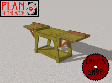
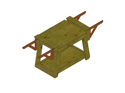
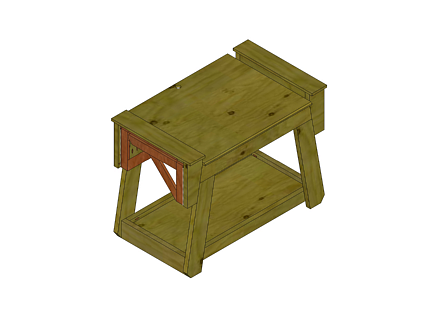
Miter Saw Stand |
|
|
Part Two: Extensions |
|
|
 |
|
|
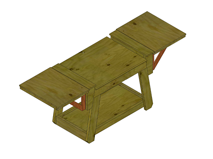
This project is Part Two of a three-part project for a miter saw stand. The first installment was the base and the last is a hood for the back. |
|
|
|
Follow ALL SAFETY GUIDELINES AND RECOMMENDATIONS provided by the manufacturers of your tools, and any chemicals such as glue and finishes you use in this project. YOU are responsible for your safety, so use common sense when working in the shop! |
|
|
|
 |
|
|
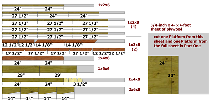
Cutting Diagram |
|
|
|
 |
|
|
Instructions
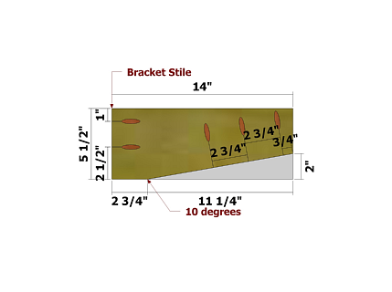
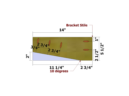
Use the layouts for creating the Bracket Stiles. Make two of each. Use a taper jig on a table saw or a jigsaw to cut the taper. Set your Kreg Jig and drill bit for 1 1/2" stock for the pocket holes on the tapers, and 3/4" stock for the pocket holes on the ends. NOTE: The 2 3/4" side shown here is determined by the size of your miter saw. Set your miter saw in place and measure the height of its base. Adjust this distance (the 2 3/4 dimensions) as needed to match the height of your saw, but do not alter the remaining dimensions for the Bracket Stiles.
|
|
|
|
 |
|
|
 |
|
|
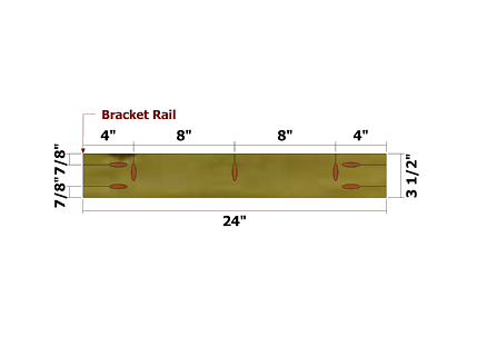
Use the layout for creating the Bracket Rails. Set your Kreg Jig and drill bit for 1 1/2" stock on the ends, and 3/4" stock for the vertical holes.
|
|
|
|
 |
|
|
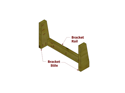
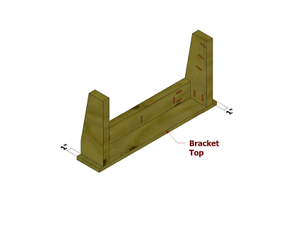
Position the parts as shown and attach using glue and 2 1/2" pocket hole screws. Create two assemblies.
|
|
|
|
 |
|
|
Position the parts as shown and attach using glue and 1 1/4" pocket hole screws.
|
|
|
|
 |
|
|
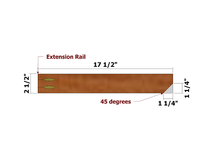
Use the layout for creating the Extension Rails. Set your Kreg Jig and drill bit for 3/4" stock. Create two Rails as shown, and two Rails as mirror images (with pocket holes on the opposing face).
|
|
|
|
 |
|
|
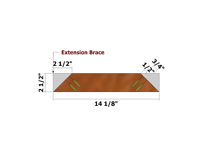
Use the layout for creating the Extension Braces. The miters cut on the ends are at 45 degrees. Set your Kreg Jig and drill bit for 3/4" stock.
|
|
|
|
 |
|
|
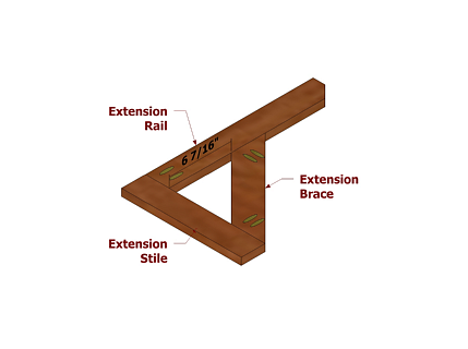
Position the parts as shown and attach using glue and 1 1/4" pocket hole screws. Create two assemblies as shown and two assemblies as mirror images of this assembly.
|
|
|
|
 |
|
|
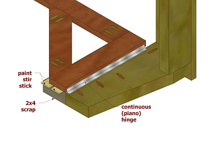
Position the parts as shown - this is for the Extension Assemblies that will be on the front-facing side of the Bracket Assemblies. Use spacers (paint stir sticks and 2 x 4 scrap in this instance) in positioning the parts. Only attach a few screws on each side of the hinge and test the movement and spacing of the hinge. The Extension Assembly should not stand proud of the front of the Bracket Stile. After you have adjusted the hinge as needed, scribe the outline of the hinge on the Bracket Stile and remove it. Leave the hinge attached to the Extension Assembly.
|
|
|
|
 |
|
|
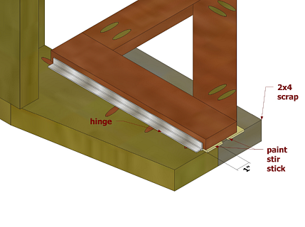
Position the parts as shown - this is for the Extension Assemblies that will be on the back-facing side of the Bracket Assemblies. Use spacers (paint stir sticks and 2 x 4 scrap in this instance) in positioning the parts. Only attach a few screws on each side of the hinge and test the movement and spacing of the hinge. The Extension Assembly should 1" from the front edge of the Bracket Stile. This will allow room for the other Extension Assembly. After you have adjusted the hinge as needed, scribe the outline of the hinge on the Bracket Stile and remove it. Leave the hinge attached to the Extension Assembly.
|
|
|
 |
|
|
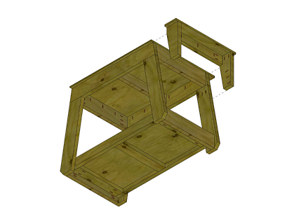
Position the Bracket Assemblies as shown, making sure the Bracket Stiles where the front-facing Extensions Assemblies were attached are in fact on the front. Position the bottom part of the 2 3/4" edge of these Stiles flush with the bottom edge of the top on the base. Attach with 2 1/2-inch pocket hole screws through the Stiles, then test to make sure the Bracket Tops are level with the base of your miter saw. Adjust if needed, then drive three more 2 1/2-inch pocket hole screws through the Brack Rail and into the Base Top End Rail.
|
|
|
 |
|
|
 |
|
|
Reattach the extension assemblies.
|
|
|
 |
|
|
 |
|
|
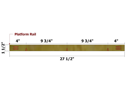
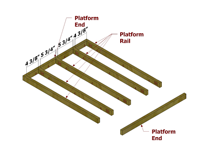
Use the layout for creating the Platform Rails. Set your Kreg Jig and drill bit for 3/4" stock.
|
|
|
 |
|
|
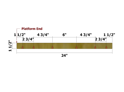
Use the layout for creating the Platform Ends. Set your Kreg Jig and drill bit for 3/4" stock.
|
|
|
 |
|
|
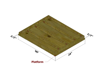
Position the parts as shown and attach using glue and 1 1/4" pocket hole screws.
|
|
|
 |
|
|
Position the Platform as shown and attach using glue and 1 1/4" pocket hole screws.
|
|
|
 |
|
|
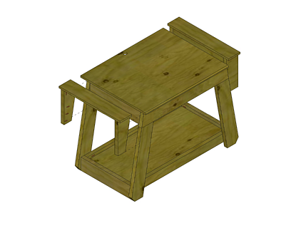
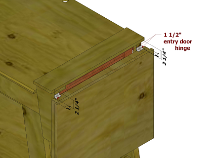
Position the Platform Assemblies as shown (widest part of the assembly adjacent to the Bracket Assembly) and attach to the Bracket Assemblies using 1 1/2-inch entry door hinges. Test to make sure the Platform Assembly is level with the top of the Bracket Assembly.
|
|
|
 |
|
|
 |
|
|
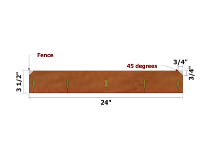
Use the layout for creating the Fences. Set your Kreg Jig and drill bit for 3/4" stock.
|
|
|
 |
|
|
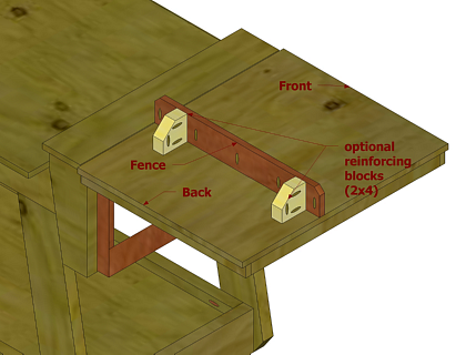
Position your miter saw on the Base Assembly and secure in place using nuts and bolts. If it is a sliding saw, make sure it does not extend past the back of the assembly when fully slid back. Use a square to make sure it is square with the Base Assembly. Line up the Fences with the fence of your saw and attach using 3/4" pocket hole screws only. If desired, attach 2 x 4 reinforcing blocks to both the Fence and the Platform using 3/4" pocket hole screws only. Set up a long board on the saw and test it to make sure the board is flush with the fence on the saw and the Fence on the stand.
|
|
|
 |